One of the projects I’ve been working on for the past few years is a small rover platform and I’ve never actually written about it. I tend to bounce between projects as the mood hits me, which means I really don’t have a lot of time for writing anyway. That’s unfortunate, especially for my projects that are long-lived endeavors. So let’s give this one a try.
The Basics
My original idea of the rover was just to have a small wheeled robot that would provide a platform for experimentation. You know, something that could roll around the house with a bunch of sensors taking in the environment around them and acting on that data. I wasn’t aiming for anything really elaborate… though I will admit the occasional visions of grandeur did (and still do) pass through my mind.
I like to do things myself, so early-on I knew that I would need to build all of the electrical and mechanical systems from scratch. Yes, I could have started with one of those “robot” base kits that are available, and maybe that would have been “easier” in the beginning. But where’s the fun in that? You don’t really learn that much when you use off-the-shelf components. And I knew that I could never customize that as much as I would want to, depending on where I went with the project.
The Mechanicals
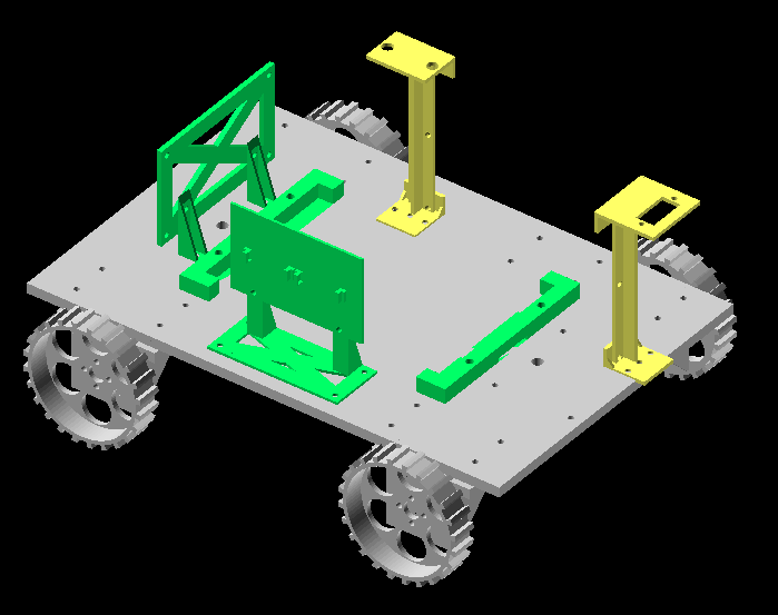
I set out to build the mechanics from the ground-up in OpenSCAD. That way, all of the components could follow a parametric design pattern which would make them easy to change when needed. I use OpenSCAD for all of my modelling anyway, so that was the logical choice. I designed the various components as time permitted, over several months.
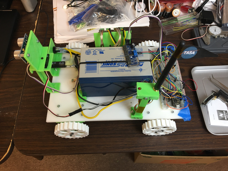
The base platform is simply a 1/4in thick plate of Delrin which was ran through my CNC machine to drill the mounting holes for various starter components; motor bracket mounts, battery mounts, and several groups of 2inx4in spaced mounting holes which would be used to mount other items that came along.
I ended up with a four-wheeled design for the rover. Each wheel is driven directly by a geared DC motor, located inside a simple mounting bracket bolted under the base platform. The left-hand motors are driven by one H-bridge controller and the right-hand motors are configured the same way, so it’s a skid-steer design. That’s fine for now, but eventually I may switch to an active steering design where each motor is driven and can swivel independently for steering.
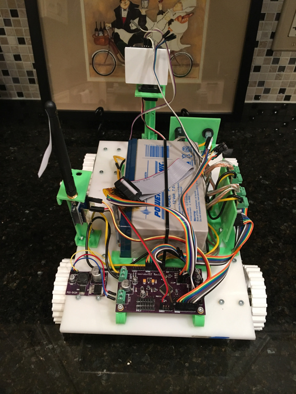
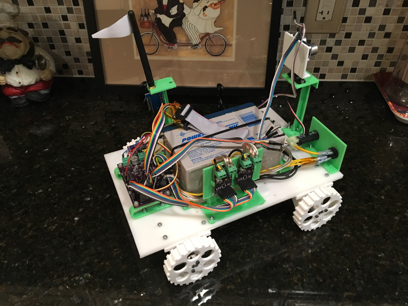
As the project has progressed, I’ve design various other mounting brackets and booms to hold the boards and sensors that make up the system.
The Electronics
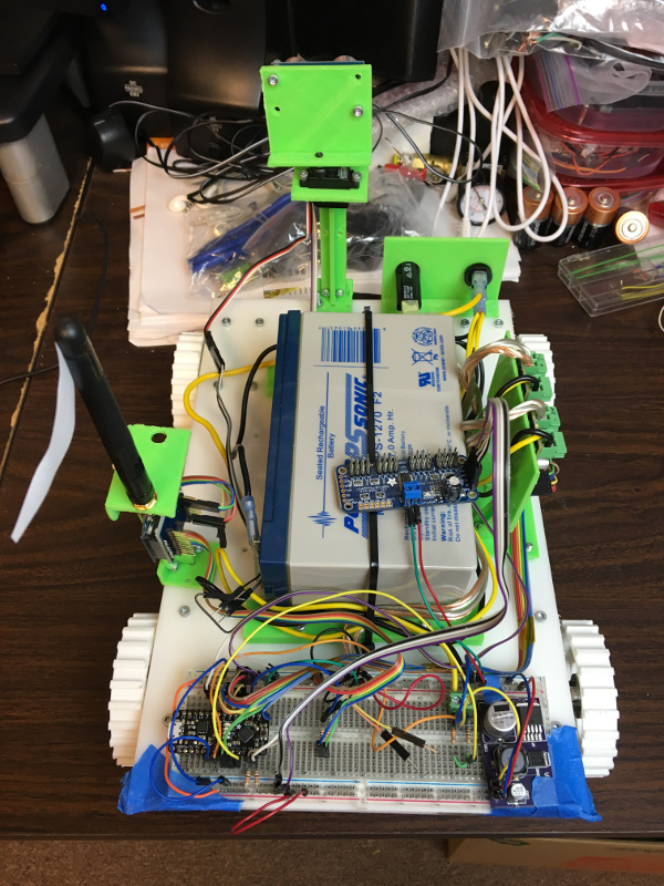
The system is powered with a 12v 7AH SLA battery. That’s probably a little bigger than needed, but I already had one sitting on a shelf. I added a switch and 10A circuit breaker in order to power the system on and off and mounted them with a 3D printed bracket.
Voltage regulation down to 5v came by way of my AP3003-based regulator board (https://random.engineer/2014/12/an-ap3003-based-switching-power-suppy/). This is one of the great benefits of designing single-purpose boards, they can be reused pretty much anywhere. And when I design a board, especially the single-purpose one’s, I typically buy enough parts to assemble two or three of them at one go.
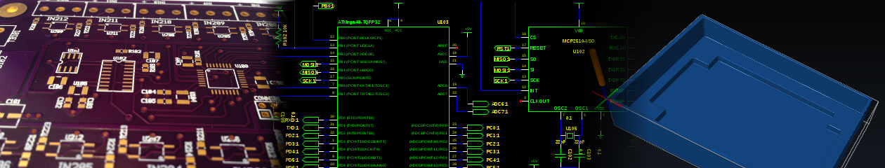
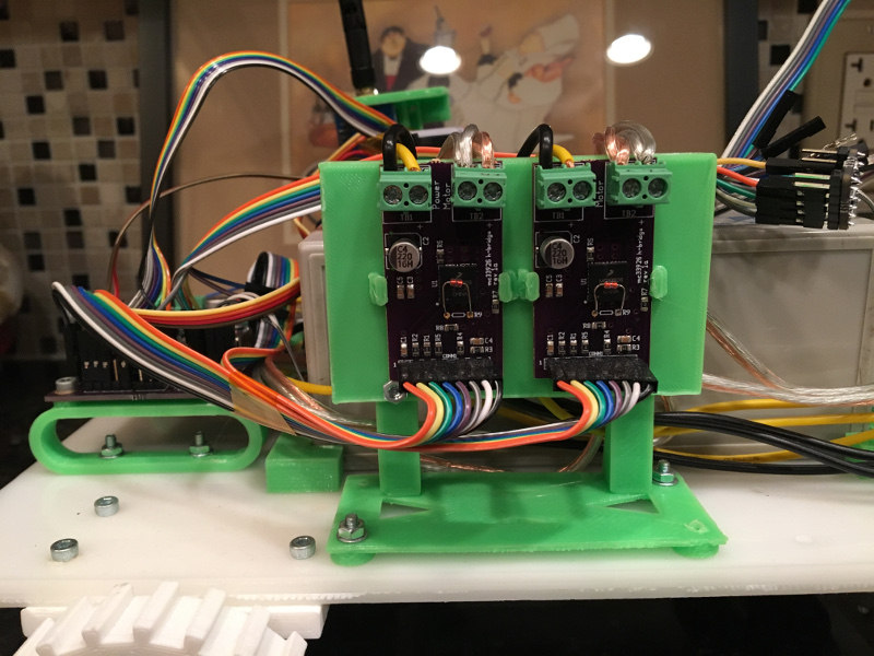
Next up was to design an H-bridge motor controller board. I created a small board based around the MC33926 IC. I wanted to be able to instrument the various subsystems of the rover and in addition to providing over-current/short-circuit feedback, the IC also provides a scaled current feedback output. I added an NTC thermistor to the board to allow me to monitor the temperature of the H-Bridge IC as well. (TODO: Do a write-up on the H-Bridge board in the future.)
Once the motor controllers were complete, I breadboarded a basic ATMega328P circuit which would be the rover’s first “brain”. I cobbled together some of my existing library code to build a small test harness that could be used to test/validate that the motor boards were working as expected. Everything was tested and working as designed. With a long serial cable connecting the rover to my laptop, I could command it to move forward, backward and rotate either left or right.
I continued to use that AVR breadboard on the rover for quite some time. I was able to experiment with an ultrasonic distance sensor and eventually added a small R/C servo which allowed me to swivel the distance sensor. Along the way, the rover’s codebase started to materialize and take shape.
Pretty soon after the rover became mobile, I switched out the serial cable for a XBee Zigbee wireless board, which allowed me to control the rover untethered. I wrote a simple application in Python which would receive the rover’s telemetry packets, displays that data and allowed me to send simple movement commands to the rover; forward, backward, left, right and stop.
The Complication (or where does the ’32’ in minrobot32 come from)
As time passed, I continued to whip the codebase into shape and eventually began dreaming of adding more sensors to the system. What about GPS, inertial measurement and more distance sensors?
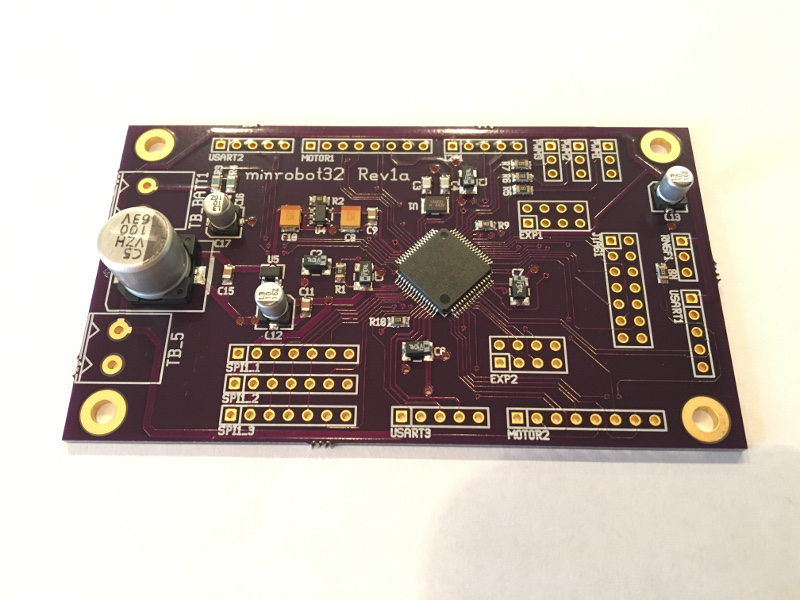
It became apparent that the ATMega328 was going to run out of I/O pins. Being comfortable with the ATMega MCUs, I first started researching larger packages for that line. Yes, I could get a 100pin ATMega package that would definitely give me plenty of I/O, but as I looked over my ever-growing “want-to” list I realized that what I really needed were more of the “complex” MCU functions. I would need more timers, USARTs, and SPI and/or I2C buses in order to accommodate all the experimenting I wanted to do with the rover. It was time to start looking elsewhere…
Up to that point, most of my embedded work had been around 8bit MCUs and I had always wanted to move into using “bigger” processors. So, I decided this was the point where I would take that on.
The ARM Switch
For many years, I had been wanting to try an ARM processor in a project. After doing some research on the various processor lines, their features and appropriate tooling, I decided to go with a Cortex-M3 processor, the STM32L100 in particular.
I ordered an STM32L100RC-DISCO evaluation board which would allow me to get started with the processor immediately, though my final intention was to design a board specifically for the project.
After setting up a GCC cross-compiler environment, I spent several weeks testing various existing ARM libraries. Shortly thereafter, I decided I would also design a purpose-built library rather than using an existing one, as I just didn’t find anything that I could really get behind. That’ll be the subject of a future post as well.
During the time I was working on the ARM library and the rover code refactoring, I also went ahead and designed the first revision ARM-based controller board, which replaced the AVR breadboard.
Conversion of the rover code from AVR->ARM was straight forward, due to the initial code layout, and I made several improvements along the way which continue to this day. A servo was added, which allows the distance sensor to sweep ~180 degrees from the left, across the front and to the right of the rover. My intention for the near future is to add static left, right and rear distance sensors.
Until next time…