In most of my past projects, I’ve been using basic linear regulator circuits for voltage regulation. That has worked fine up to this point, but now a couple of my projects are needing to use higher voltages for some components. A good example is my CNC machine, which uses 24v for the stepper motors. I had designed my own AVR-based controller board (running GRBL), but after running it for a while I realized that the linear regulator was getting too hot for my tastes. I could increase the pad size on the regulator a little, which would have provided better thermal dissipation, but I decided it was time to try a different approach. Everybody likes to play with new hardware, right?
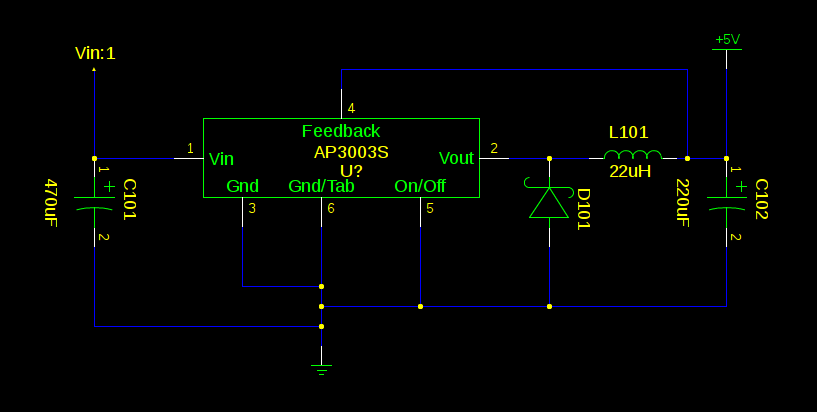
I started searching for buck regulators and ran across the Diodes Inc. AP3003S switching regulator. After reading through the datasheet, I decided this part would cover my needs. For the 5v output version, the input voltage range was 7-32v and the current capacity(2A) was well over what I needed. I set out to build an initial circuit around that part, basically using the reference design from the datasheet. After a few minutes of layout time in gschem and playing with various part placements in PCB, I ended up with the schematic and PCB layout shown below.
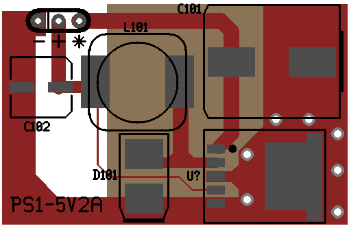
A fair amount of copper was placed on the board to provide heat dissipation for the AP3003S, even thought I don’t expect to push too much current through it. Once the boards come back from the fab house and are assembled, I plan to run the board through it’s paces on the test bench.