I’ve been using surface mount components on my boards for a while now and using a syringe and needle to deposit solder paste has worked fairly well. But it’s a pain using that technique for fine-pitched components. I ran across https://www.oshstencils.com/ and decided it was time to try using a solder stencil. A copy of my board’s paste mask was uploaded to the site and a few days (maybe a week) later, I received the solder stencil.
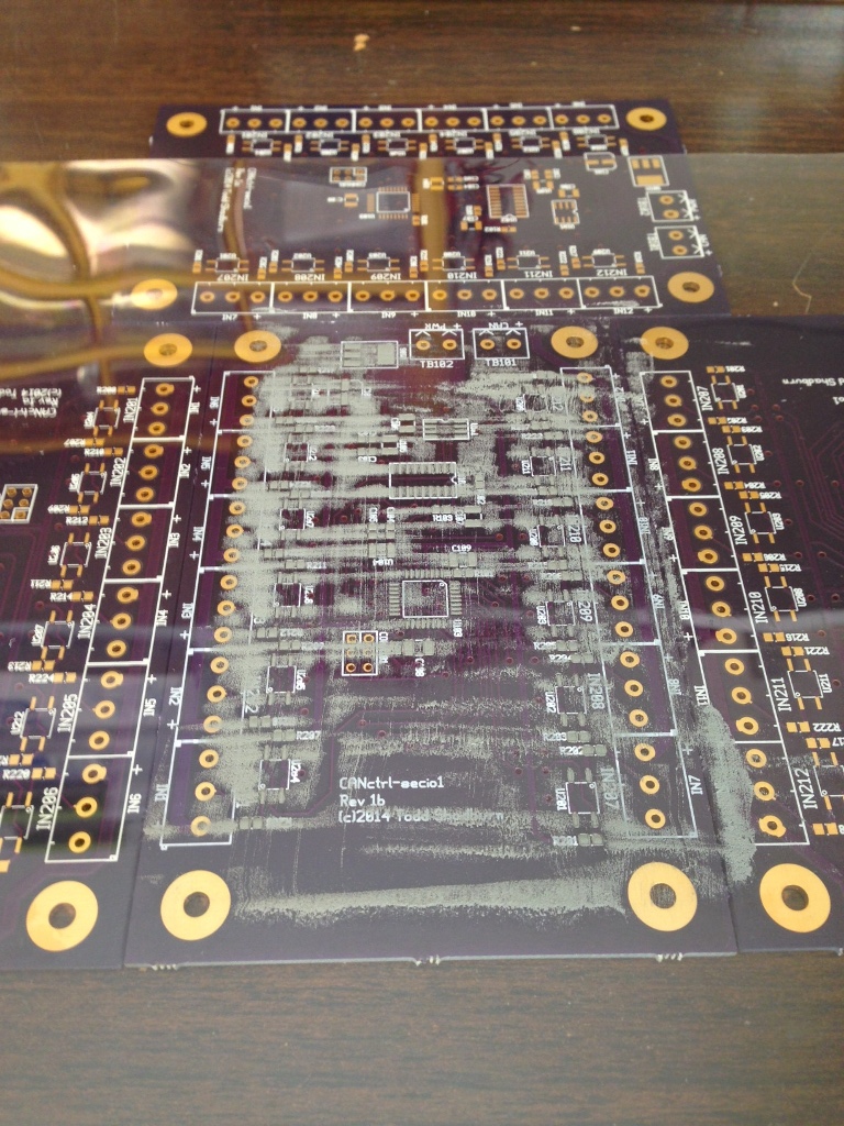
Below are the results of using my first SMD solder stencil. I was as careful as possible throughout the process. And either it was that, or beginners luck, but I really didn’t run into any problems and the results turned out great… even the fine-pitch components worked perfectly.
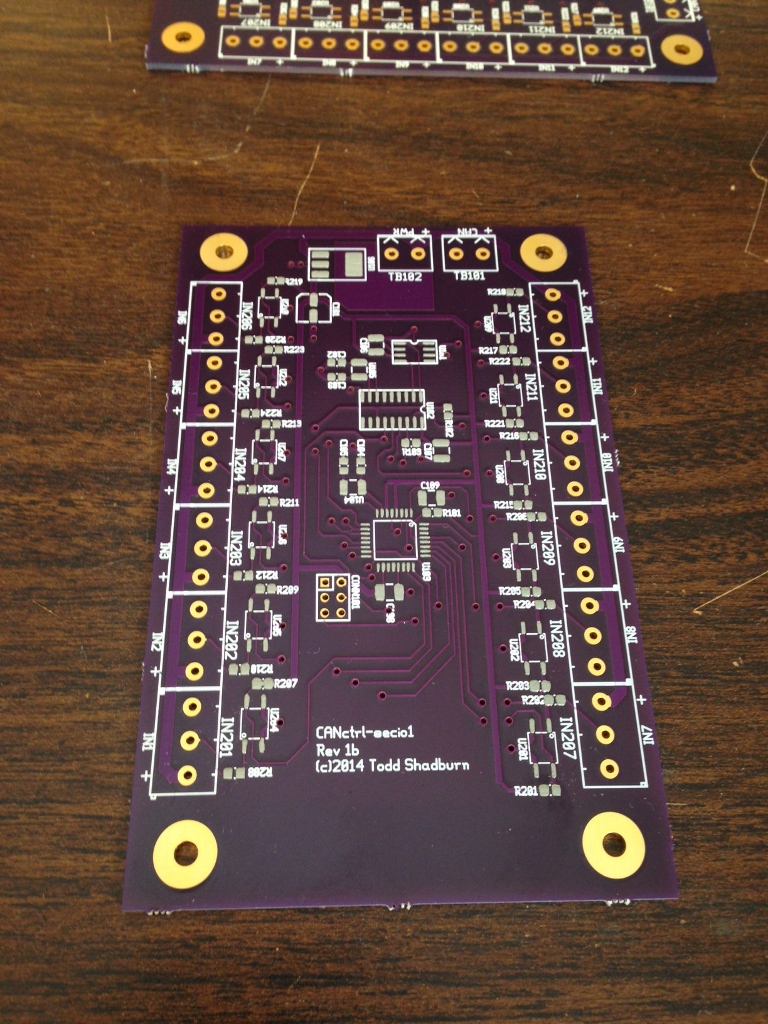
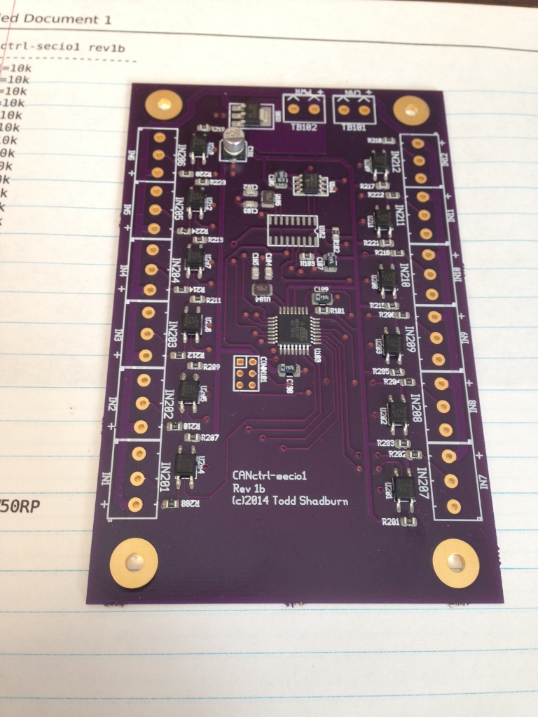
First, several boards were placed around the board to be pasted, to provide a level surface around the edges of the board. Then the stencil was placed on top of the board and carefully aligned with the component pads. Next, a thick bead of solder paste was deposited onto the stencil, along the top width of the board. I also rechecked the stencil alignment at this point. Finally, while holding the stencil securely in place, the paste was pulled across the face of the stencil with a squeegee.
During the first pull, the squeegee was held at around a 45 degree angle to the face of the board, which ensured a nice even paste coverage. Then the squeegee was pulled back across the face at an almost 90 degree angle, which removed most of the excess paste.
Still holding the stencil firmly at one end, it was pulled up and away from the board starting at the other end, so as not to smear the paste.
The next step was to place the components onto the board. I usually start with the smallest components first (resistors, capacitors, etc), then move on to the larger ones.
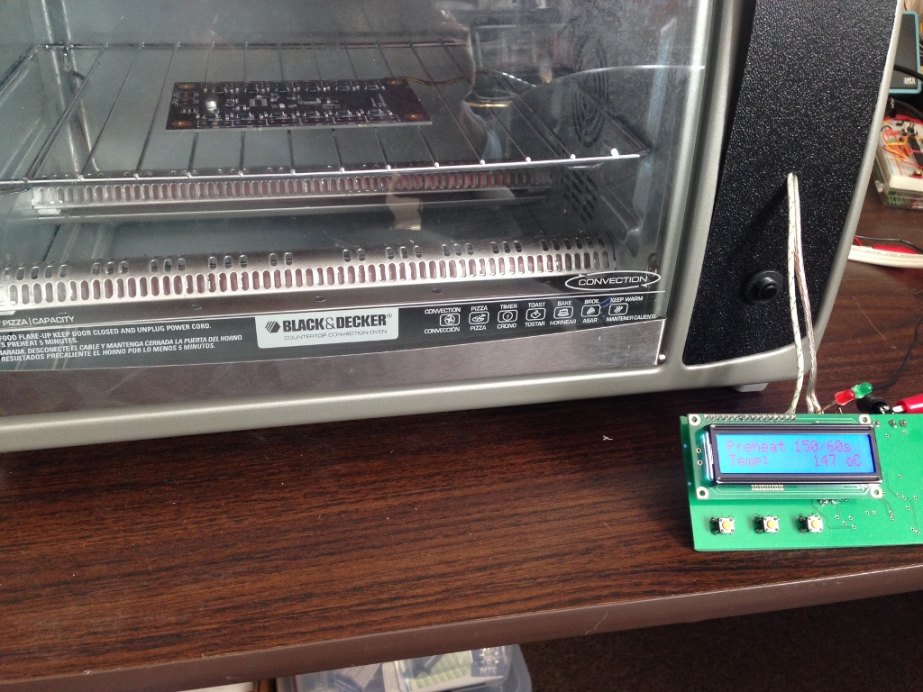
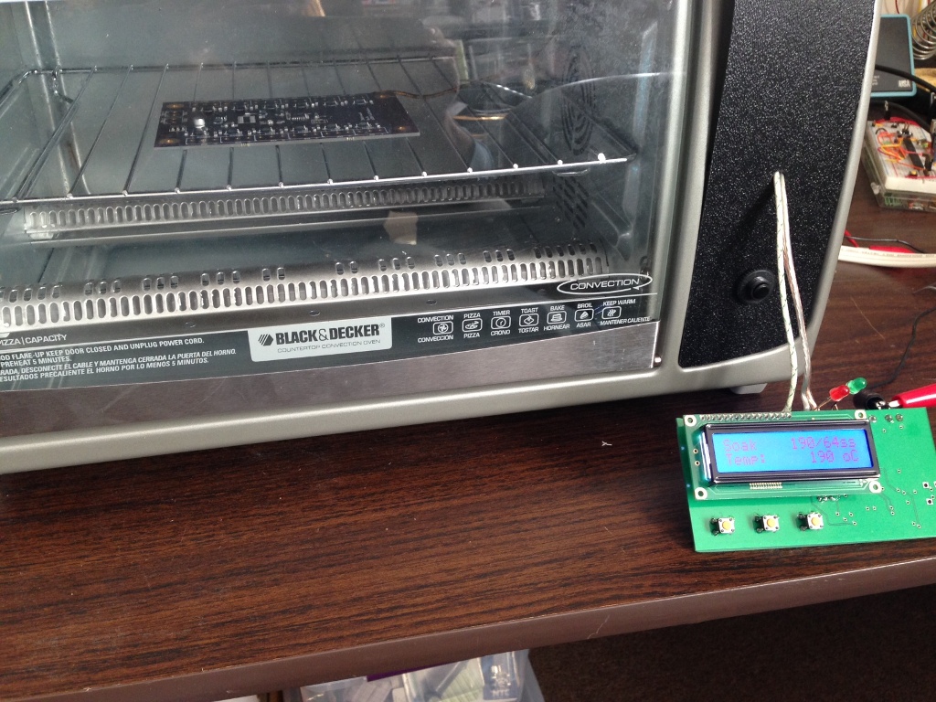
Now it’s into the reflow oven!
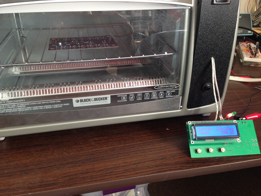
Once the reflow was complete, the board was removed from the oven and allowed to cool a bit.
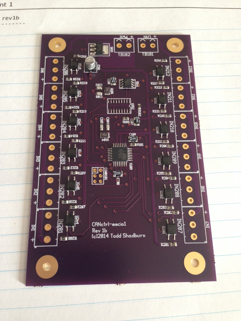
So, an initial success with solder stencils. I’ve got a few more designs in the queue and am looking forward to seeing how those turn out as well.