A couple of weeks ago, I received a free Pro Trinket with one of my Adafruit orders. A few days later, I was looking for a quick voltage data logging circuit to use for testing another project. I remembered the Trinket and decided to us it as a quick test bed for an analog to digital convert.
Hardware
I worked up the following circuit on a breadboard. It’s basically a Pro Trinket, an FTDI USB-serial adapter and a couple of resistors. (I already had a serial library and didn’t want to mess with using V-USB… maybe another time.)
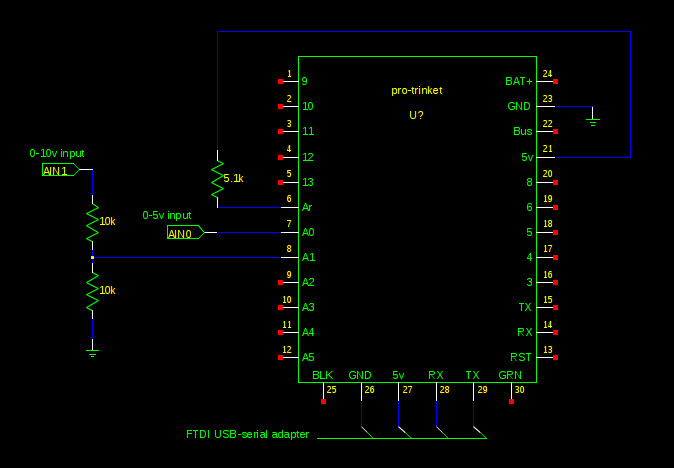
The 5.1k resistor provides the ADC reference voltage to the AVR. It’s not needed if you configure the AVR to use the internal reference from the AVCC pin. The AVR code provided later in this article supports both reference voltage methods. If you decide to use the external resistor, remember the AVR has an internal 32k resistor between the reference connection and GND, which forms a voltage divider. Calculate the external resistor value for your own usage.
The analog inputs A0 through A5 are used to provide the analog inputs. For input voltages that exceed the reference voltage, you’ll need to use a voltage divider network to scale the voltage down to be within the ADC range (0v – 4.32v for my 5v Trinket circuit shown above). The schematic above shows such a divider network attached to the A1 pin, which allows a 0-8.64v input to be measured with the values given. Again, calculate the resistor values you need for your use case.
AVR Firmware
I cobbled together a few of my existing serial functions and a couple of ADC functions together, and ended up with the following code, which I flashed onto the trinket using avrdude. The Trinket bootloader appears as a USBtinyISP to avrdude.
/*
 *
 * adcsampler.c
 *
 * ADC sampler main source
 *
 * Copyright 2013,2014,2015 Todd Shadburn
 *
 * Licensed under the GNU GPL version 2
 *
*/

#include <avr/io.h>
#include <avr/interrupt.h>
#include <avr/pgmspace.h>
#include <util/delay.h>
#include <stdint.h>
#include <stdlib.h>
#include <stdio.h>
#include <string.h>

// Set this to the AVR analog reference voltage
//#define VREF   2.59
#define VREF   3.170

#define BAUDRATE 9600
#define BAUD_PRESCALLER (((F_CPU / (BAUDRATE * 16UL))) - 1)

// Defines for selecting reference inputs
#define ADC_REF_EXTERNAL    0
#define ADC_REF_AVCC        1
const char msg_initstr[] PROGMEM    = "ADCsamplr v0.1\r\n";
const char msg_author[] PROGMEM        = "(c) tshadburn\r\n";
const char msg_adcraw_header[] PROGMEM    = "adc-raw,";
const char msg_adcraw_element[] PROGMEM    = "%d,";
const char msg_volts_header[] PROGMEM    = "adc-volts,";
const char msg_volts_element[] PROGMEM    = "%f,";
const char msg_crlf[] PROGMEM        = "\r\n";


void serial_init(void)
{
    UBRR0H = (uint8_t) (BAUD_PRESCALLER>>8);
    UBRR0L = (uint8_t) (BAUD_PRESCALLER);
    UCSR0A &= ~(_BV(U2X0));            // disable baud doubler (<57600 baud)
    UCSR0B |= (_BV(RXEN0)|_BV(TXEN0));
    UCSR0C |= (_BV(UCSZ01)|_BV(UCSZ00));
    return;
}


void serial_write_byte(unsigned char data)
{
    while (!(UCSR0A & _BV(UDRE0)));
    UDR0 = data;
    return;
}


void serial_write(char *str)
{
    while (*str != 0x00) {
        serial_write_byte(*str);
        str++;
    }
    return;
}


void serial_write_P(const char *str)
{
    while (pgm_read_byte(str) != 0x00) {
        serial_write_byte(pgm_read_byte(str));
        str++;
    }
    return;
}


void adc_init(uint8_t reference)
{
    // Default is to use the external Aref (internal Vref disabled)
    ADMUX = 0;
    // If requested, enable internal Vref
    if (reference == ADC_REF_AVCC)
        ADMUX |= _BV(REFS0);
    // Disable power reduction
    PRR &= ~_BV(PRADC);
    // Disable digital input circuits (reduce noise/power)
    DIDR0 |= _BV(ADC0D)|_BV(ADC1D)|_BV(ADC2D);
    DIDR0 |= _BV(ADC3D)|_BV(ADC4D)|_BV(ADC5D);
    // Prescale system clock by 128 and enable ADC
    ADCSRA |= _BV(ADPS0)|_BV(ADPS1)|_BV(ADPS2)|_BV(ADEN);
    // Take an initial sample to init the hardware
    ADCSRA |= _BV(ADSC);
    while ((ADCSRA & _BV(ADSC)));
    return;
}


uint16_t adc_sample_channel(uint8_t channel)
{
    uint16_t result = 0;
    if (channel > 8)
        return result;
    ADMUX &= 0xf0;    // first zero channel bits
    ADMUX |= channel; // select channel
    ADCSRA |= _BV(ADSC); // start conversion
    while ((ADCSRA & _BV(ADSC))); // wait for conversion completion
    result = ADCL;
    result += (ADCH & 0x03)<<8;
    return result;
}


int main(void)
{
    uint8_t        i;
    uint16_t     res[8];
    float        volts;
    char        str[32];

    // System initialization
    serial_init();
    sei();
    adc_init(ADC_REF_AVCC);

    // Display startup message
    serial_write_P(msg_initstr);
    serial_write_P(msg_author);

    while(1) {
        // sample all channels
        for (i=0 ; i<5 ; i++) {
            res[i] = adc_sample_channel(i);
        }

        // write adc-raw output line
        serial_write_P(msg_adcraw_header);
        for (i=0 ; i<5 ; i++) {
            sprintf_P(str, msg_adcraw_element, res[i]);
            serial_write(str);
        }
        serial_write_P(msg_crlf);

        // write adc-volts output line
        serial_write_P(msg_volts_header);
        for (i=0 ; i<5 ; i++) {
            // Vin=(adc*Vref)/1024
            volts = ((float)res[i] * VREF) / 1024.0;
            sprintf_P(str, msg_volts_element, volts);
            serial_write(str);
        }
        serial_write_P(msg_crlf);

        _delay_ms(1000);
    }

    return 0;
}
After loading the firmware and connecting the FTDI adapter to my laptop, I fired up minicom and connected to /dev/ttyUSB0 at 9600 8N1 and data lines began to be displayed. The AVR code outputs two lines to the serial port every second, both of which are comma-separated lists consisting of a line identifier and the ADC values for AD0 through AD5 (in that order). The ‘adc-raw’ line provides the raw ADC sample values (0-1023) and the ‘adc-volts’ line provides the voltage sampled at each input. The ‘adc-raw’ line was really just for debugging, but I’ve left it in just in case I wanted to log the raw data. Remember, the voltage values from the ‘adc-volts’ line will be scaled down if you are using a voltage divider at any of the inputs.
Host Capture Software
Now that I was getting data to the laptop, I wanted to be able capture the data to a file for later use; review, graphing, etc. So, I whipped up a quick Python script which would grab the sample data from the serial port and write the output to the terminal. I also added the ability to provide a scaling multiplier for each of the ADC channels, which allows me to compensate for any voltage dividers used on the ADC inputs.
#!/usr/bin/python
#
# adcsampler.py - read ADC data from the adcsampler AVR circuit
#
# Copyright 2015 Todd Shadburn
#
# Licensed under the GNU GPL version 2
#

import sys
import serial

MAX_ADC_CHANNELS=8

if len(sys.argv) < 2:
  print "Usage: adcsampler.py device [channel#=multiplier] ..."
  sys.exit(2)
device=sys.argv[1]

# Initialize multiplier list
multiplier = []
for i in range(MAX_ADC_CHANNELS):
  multiplier.append(1.0)

# Read new multiplier values from command line
for i in range(2, len(sys.argv)):
  if '=' in sys.argv[i]:
    c,v = sys.argv[i].split('=')
    print 'Setting ch#%d multipier to %f' % (int(c),float(v))
    multiplier[int(c)] = float(v)

ser = serial.Serial(device, baudrate=9600, timeout=2)
while 1:
  for line in ser:
    if 'adc-volts' in line:
      avf = line.split(',')
      for i in range(1, len(avf)-1):
        print 'CH%d: %f' % (i-1, float(avf[i]) * multiplier[i-1])
ser.close()
sys.exit(0)
The script expects (at least) the path to your FTDI serial device (/dev/ttyUSB0 in my case). And once executed, it will begin printing sample data to the console, which I can redirect to a file for saving the data. The script can also accept ‘channel#=multiplier’ arguments and those multipliers will be applied to the received voltage values before being output.
An example of the script usage and output is shown below. I just use CTRL+C to kill the script when I’ve captured all the samples I need.
python ./adcsampler.py /dev/ttyUSB0
CH0: 1.656201
CH1: 0.000000
CH2: 0.000000
CH3: 0.000000
CH4: 0.034053
CH0: 1.656201
CH1: 0.000000
CH2: 0.000000
CH3: 0.000000
CH4: 0.034053
And here’s an example of using a 2x multipler with channel #0 (I had a pair of 10k resistors connected as a voltage divider, so the ADC voltage needs to be multiplied by 2 in order to get the correct voltage in the output.
python ./adcsampler.py /dev/ttyUSB0 0=2.0
Setting ch#0 multipier to 2.000000
CH0: 3.306210
CH1: 0.000000
CH2: 0.000000
CH3: 0.000000
CH4: 0.034053
CH0: 3.300020
CH1: 0.000000
CH2: 0.000000
CH3: 0.000000
CH4: 0.034053
And that’s it. I’ve got a quick and dirty circuit to use for ADC data logging. The script provides the ability to scale the output for each channel, so if I have several voltage levels that need to be measured, I just use a proper divider network and then tell the script what multiplier is needed to re-scale the output values.